PHILIP : Powering
Rovers by High Intensity Laser Induction on Planets
by using High Intensity Laser Power Beaming System
Funding organization: European Space Agency (ESA)
Coordinator: Leonardo S.p.A,
Italy
Partner:
INOE 2000, Romania
Project manager for partner: Dr. Mariana Braic
Team:
Dr. Viorel Braic - Key person,
Dr. Iulian Pana.
ABSTRACT
The scenarios that have been identified anticipate operations on
the south polar surface of the Moon, including areas where solar energy collection
presents challenges, such as Permanently Shaded Regions (PSR).
Investigating PSR is the goal. Traditional powering systems
require the rover to periodically exit the PSR for batteries replenishment.
Using radioactive materials as a power source is an alternative strategy. One
example of this is the plutonium Multi Mission Radioisotope Thermoelectric
Generator installed on the NASA/JPL MSL mission's Curiosity Rover.
In addition to the aforementioned, large batteries would be
required for the rover to travel deep within the PSR, which would make
designing the vehicle extremely challenging in terms of mass and volume.
In PHILIP project a novel strategy is investigated: using a high power laser beam that is directed out of the lander and
into the rover's line of sight, the rover can be powered continuously, allowing
it to enter the PSR without interruption and without the need for radioactive
materials.
Designing an optical system with the goal of expanding the laser
beam out of the fiber connector to a defined diameter and orienting it toward
the rover using steering mechanisms is the task assigned to INOE 2000.
The laser beam diameter must be designed to ensure the minimum
divergence, allowing the photovoltaic panel to collect the same amount of power
density on the photovoltaic cells along the rover range excursion, in order to
illuminate the rover within 4 km of the target distance or 15 km.
RESULTS
Initial plan: After the first beam expander (Bex), the movement of
the plane mirror revealed a significant shift in the beam position at large
distances, which was deemed unacceptable when taking into account a 40 mm laser
beam (wavelength 1070 nm) diameter. In this model, a PV panel with a lateral
dimension of 0.54 meters was taken into account. Additionally, since the BEx#2 and the steering mirror
should only have one moving platform, the mass of the selected mirror was
deemed prohibitive.
Our calculations indicated that for a maximum laser beam
deflection of 0.0040, the beam will stay on the panel, taking into account the
potential angular movement of the mirror and the requirement for the image to
remain on the PV panel. This angular value, however, was deemed unacceptable
since it would place severe restrictions on the steering mechanism's ability to
move accurately.
A second design with a mix of parabolic mirrors was released. The
parabolic mirrors M1 and M2 were the ideal arrangement. The selected reflected
focal length (F1) for M1 was also calculated issuing a feasible value from the
point of view of manufacturing constraints.
The M1 mirror's diameter was selected due to its excellent fit
with the incident collimated beam diameter. Additionally, a small F1 value
makes it possible to obtain a compact setup system in terms of mass and size by
allowing for a short distance to the second mirror. To enable the optical setup
to have a compact structure, an extra plane mirror was added. We made use of
mirrors, which reputable manufacturers can provide.
Several image diameters (ID) at 5, 10, and 15 km, were calculated
using the design with two parabolic mirrors. Several input beam diameters
supplied by a collimated laser source were taken into consideration. The
variation of the PV panel's image diameter (ID) at 4 and 15 km, as well as the
necessary magnification, were calculated to determine the optimal value of F2.
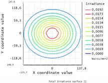
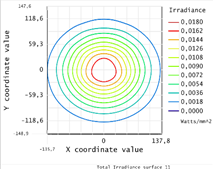
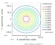
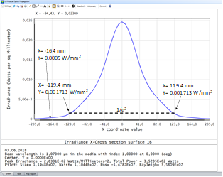
The calculated image diameter (ID) at 4, 10, and 15 km, as well as
the irradiance, are modeled in the figure below, taking into account the two
parabolic mirrors with optimized focal points (Fi) and a certain collimated
laser beam diameter. The Gaussian beam profile at 15 km distance from the laser
is also shown.
|
4 km |
10 km |
15 km |
|
|
|
|
|
|
|
ID = X mm |
ID = X+7 mm |
ID = X+17 mm |
|
The optical setup was viewed as a single module to maintain the
components' constant positions. The laser beam collimator, which is attached to
the laser exit via an optic fiber (FO), is housed on the base plate of the
optical system. A plane mirror deviates the beam that emerges from the
collimator at a 90-degree angle. In order to connect to their holders, the two
parabolic mirrors should be fitted with appropriate tapered holes and machined
to the lowest mass permitted.
Conceptual optical arrangement taking the needs for steering into
account: There were two distinct steering requirements: coarse mode and fine
mode. In the coarse mode, a gimbal holder rotates the optics base in two
planes. After accounting for the scanning process that keeps the laser beam in
contact with the PV panel, we have determined that few tens of nm resolution of
a piezo actuator causes a shift in position of less
than 10-7 radians. Given that a position change of about 10-5
rad is required to move the laser beam along half of the PV panel, resulting
that the piezo-actuator's resolution is found to be adequate. Additionally, the
piezo actuators could be commercially available vacuum-compatible piezo-motors.
To track the rover's movement in the fine mode without losing
contact with the PV panel, the beam needs to have an appropriate moving
resolution. A solution with the base plate positioned on a platform resembling
the base plate emerged, taking into account the rover's speed and distances as
well as the requirement for beam steering in two planes. Although the solution
is comparable to the currently available tilt and rotate optical holders sold
in stores, it needs to be modified to account for the optical setup's weight
and dimensions. A setup for precise positioning was also defined.